The TAU: A Perfect Solution for Fast, Strong, and Inexpensive Thermocouple, Stud, and Pin Welidng

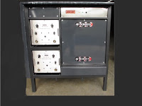
Thermocouple attachment unit (TAU)
Thermocouple attachment unit (TAU) used for creating
thermocouples quickly and inexpensively, plus welding
studs and pins to metal structures.
Are you buying pre-made thermocouples? Do you know how easy it is to make your own? Are you always looking for a fast and easy way to attach studs or pins to a target structure? A thermocouple attachment unit (TAU) is the answer. TAU’s will help you save time and money in the fabrication of welding thermocouples and stud/pin welding.

Thermocouple attachment units (TAUs) are small, self contained spot welders that achieve superior results for welding thermocouple junctions and attachment. They are portable and are easy to use. Also known as thermocouple welders, these units are provide a capacitive discharge (as the energy source) in a compact, self-contained, hand welding unit. They are designed to form very strong, free standing junctions in just seconds using standard thermocouple wire. There's no need for clamping, bracketing or strapping. TAUs provide a direct bonding method for thermocouples, pins and studs that is quick, easy, and low-cost while still providing accurate temperature measurement.

Thermocouple attachment units continue to enhance their power outputs which creates more potential uses for TAUs. Higher power output opens doors to a broader application base. Higher power TAUs can be used to weld thermocouple pairs but also can be used to weld studs, rods and pins to a wide variety of metal structures. For example, a common use for TAU’s is attaching insulation pins to welding insulation blanket support.

An internal power supply constantly recharges an internal battery giving the operator portability in field thermocouple welding. Readily available controls allow for easy adjustment based on wire size and material.

Thermocouple attachment units offer a very convenient and economical method of forming and attaching thermocouple sensing wires, studs, and pins where and when you need them. Models vary based on requirements. Some models accommodate a greater range of wire sizes and materials, handling wire up to 14 gauge and capable of creating weld junctions in under a second. Because the power supply provides a short recharge interval, multiple welds can be done very quickly (4-6 welds per minute).

For more information on thermocouple attachment units, contact:

Hotfoil-EHS
2960 East State Street Ext.
Hamilton, NJ 08619
Phone # 609.588.0900
Fax # 609.588.8333
Email: dap@hotfoilehs.com
www.hotfoilehs.com

Electrostatic Precipitator and Bag House Hopper Heaters Prevent Fly Ash Production Problems

hopper heaters for power plants
Coal fired power plants must manage fly ash properly.
Coal fired power plants in the United States require the use of electrostatic precipitators or bag houses to filter out very fine fly ash particulate incorporated in the flue gas. The ash is collected as the flue gas passes through filter bags or by large electrodes, and then falls into collection hoppers.

As the hot fly ash cools, condensate on the hopper walls can form. The mixture of dry, sulfur rich fly ash and water is very problematic, so it's very important to keep condensation from forming in the collection hoppers. The mixture of water and fly ash can cause clogging (or “pluggage”) in the throat of the hopper,  and more importantly, the residual sulphur in the flue gas will combine with the condensate to form sulphuric acid. The suluric acid attacks the hopper walls from the inside causing corrosion, weakening the walls and creating significant (and costly) maintenance issues over time.

hopper heaters for power plants
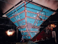
Fly ash hopper with heaters.
Efficient and continuous fly ash removal is critical for all coal fired power plants. Collection hoppers are an integral part of the removal process. Pluggage or inoperable hoppers are a known issue to engineers and maintenance crews. The constant maintenance and excess of down time seriously hinder a plant’s ability to manage the fly ash production rate. Slower fly ash production means limiting energy production and efficiency. A power plant’s electricity production is directly proportional with its coal combustion rate which, in turn, directly effects the fly ash production rate. Plant maintenance personnel usually attempt to remedy ash system failures in real time by deactivating the affected hopper while continuing to generate power and ash. In some situations (to prevent boilers shutdowns) ash will be dumped on the floor, requiring costly clean up.

The evacuation and management of fly ash is much easier when the ash is kept hot. One of the most common ways to maintain elevated fly ash and hopper temperature are electric hopper heaters attached to the external hopper walls. Hopper heaters play a very important role in the removal of fly ash from precipitators and bag filter hoppers by keeping the hopper temperatures operating above the flue gas acid dew point. The hopper heater’s sole function is to preheat the hopper and the internal environment to prevent the formation of moisture and the resulting clumping of fly ash and development of sulphuric acid.

hopper heaters for power plants
Flexible heating element used on hopper throat.
Hopper heaters are designed for the dirty, high vibration environment of a power plant. They provide the optimum watt density for proper conduction through the hopper wall and for uniform heating. The are available in square, rectangular, and trapezoidal shapes to accommodate any hopper design. Ancillary flexible heating blankets are available for poke tubes, man-ways, and cylindrical throats.

The use of electric hopper heaters on electrostatic precipitator and bag house fly ash collection systems is a time proven, effective way to prevent condensate formation and the resulting clumping and corrosive acids in hoppers, thus facilitating a better opportunity for uninterrupted fly ash production.

For more information, contact:

Hotfoil-EHS, Inc.
2960 East State Street Ext.
Hamilton, NJ 08619
Phone # 609.588.0900
Fax # 609.588.8333
Email: dap@hotfoilehs.com
www.hotfoilehs.com

Aftek at CastExpo 2016

The single largest trade show and exposition for metalcasting in the Americas, CastExpo, is being held in the Minneapolis Convention Center April 16 through the 19th, 2016.

Held every three years, CastExpo offers metalcasters, suppliers, and casting buyers and designers the opportunity to connect and educate themselves on the latest metalcasting has to offer.

Aftek Quad Arc Welder
The Metalcasting Congress technical program and additional workshops cover a wide range of topics. Identify which specific technical presentations and workshops you would attend that is relevant to your company and its immediate and future challenges.

Aftek (Division of Hotfoil-EHS) will be attending displaying their Quad Arc heavy duty arc welder, Quad Arc are:
designed for low maintenance in harsh environments. Features of the
  • Submerged arc.
  • Air arc gouging to ½” electrodes.
  • FCAW (flux core MIG) all positions, self or gas shielded.
  • Performing outstanding results on stainless, or steel castings.
  • Power sources, rated for 100% duty cycle. Amperage range adjustable in 5 amp increments.
  • Designed with Harsh Environment in mind.
  • Designed with a single transformer on the MV1500G1.
  • Powder Coated for a long lasting durable paint job.
  • Protected with thermostatically controlled alarms on the rectifiers and the transformers.
  • Designed to shut down if any of the Alarms are Energized.
  • Easy-to-reset overload breaker for circuit protection.
  • Optional protection for incoming Primary Power.
  • Dimensions 51” Wide x 40” Deep x 57” Tall.
If you're planning to attend CastExpo this year, please plan on stopping by Booth 1346 and visit. 

Custom Fabricated Gas Trains and Nozzles Capable of 10 Million BTU Output

Gas Trains designed with safety in mind. All gas trains have dual valves on the pilot line and main, low gas pressure switch, high gas pressure switch, and proof of closure.
Fully automatic units are supplied with a 4-20 mA controlled actuator that regulates gas. The control system includes a power-on switch, power-on light, master controller with 4-20mA slave controller, air-on light, gas-on light, ignition-firing light, burner-on light, high-fire light and high-fire switch. Should the limit switch fail system come with a dump button and procedure for clearing the gas out of the lines. Construction is 1.5 inch powered coated tubing.

Other features include:
  • 15HP blower motor than can move up to 2200 cubic feet/minute 
  • Damper with a handle wheel for adjustment 
  • Blower is powder coated for longevity 
  • Starter box incorporates a lockable disconnect 
  • Supplementary circuit breaker 
  • Starter contactor 
  • 750VA transformer 480/120 for power to the train. 
Burners are 316 stainless steel. Three standard sizes: 6-10 million BTU; 3-6 million BTU burner; 1 million BTU burner.


For more information. contact:
Hotfoil-EHS, Inc.
2960 East State Street Ext.
Hamilton, NJ 08619
Phone # 609.588.0900
Fax # 609.588.8333
www.hotfoilehs.com
Email: dap@hotfoilehs.com

Hotfoil Hopper Heater and Control Systems

hopper heater control system
Hopper heater control system
Here's a short video showing Hotfoil's capabilities in engineering, designing, and applying hopper heaters and control systems used in power plant applications.

All Hotfoil products are made in the USA at Hotfoil's Hamilton, NJ manufacturing facility.


Hotfoil products include:
  • Type HB Hopper Heating Modules
  • Type FRP Heating Panels
  • Type ELP Heating Panels
  • Type GA Heating Blankets
  • Type HSR / HSRX Silicone Rubber Heaters
  • Type PCW and SRC Heating Cable
  • Type MI Metal Sheathed Heating Cable
  • Tank Heating Controls
  • Hopper and Chute Heater Controls
  • Heat Control Systems for Hazardous Areas
  • Baghouse & Precipitator Hopper Heaters
  • Heaters for Coal Handling Chutes, Silos, & Conveyors
  • Tank Heating: Steel, Stainless Steel, Poly & Fiberglass
  • Heating Blankets For Conical Hoppers
  • Pipe Tracing - Constant Wattage & Self Limiting
  • Tote Heating with Silicone Rubber Heaters
  • FRP Heated Fiberglass Totes


Freeze Protection for Coal Handling Systems

coal system heating
Coal stored outdoors on the stockpile or delivered by unit train or barges picks up moisture from rain and snow. When this wet or frozen coal is conveyed, it inevitably comes into contact with the plate steel of the various hoppers and chutes within the coal handling system. During winter, this plate steel is below freezing for extended periods.

When wet or frozen coal encounters steel at sub freezing temperatures an instantaneous bond is formed. This bond causes immediate and often catastrophic blockage of the hopper and chutes. The bond and resultant blockage is so severe that pneumatic drilling equipment and explosives are often required to free up the system.

This problem, known as FLASH FREEZING, is extremely inconvenient and very costly. Several cases are documented where utility and industrial boilers have been shut down due to blocked conveying systems.

The document below describes effective electric heating systems for coal handling freeze protection.


Transformer Basics

Electric transformer
(courtesy of Aftek EHS)
Transformers are composed of an iron core ring wrapped in coils. One coil is connected to an AC input voltage and is called the primary coil. The other coil is connected to an output circuit with the load resistance, and is called the secondary coil.

The two coils are well insulated from each other and do not form a physical electrical connection. This gives a transformer its unique electricity altering properties. Transformers can either step up or step down a voltage.

In a step down transformer, the number turns in the primary coil is greater than the number of turns in the secondary coil step up transformer the number of turns in the secondary coil is greater than the number of turns in the primary coil. The constantly changing current driven by an alternating voltage source induces a changing magnetic field in the core of the transformer.

The magnetic field created by the alternating current in the primary coil generates the flux in the transformer core. The secondary coil converts the flux back into current flow and produces a voltage at the load, or resistance, in the secondary circuit.

If there are fewer coil turns on the secondary then on the primary, this is called a step down transformer. The resulting voltage in the secondary circuit will be less than the primary.

In this example we have 20 turns on the primary coil and 10 turns on the secondary coil. To determine the decrease in voltage occurring in this step down transformer, we can use a simple ratio formula. This formula simply states that the secondary voltage to primary voltage ratio, is the same as the secondary coil to primary coil turn ratio. Rearranging the formula and then dividing 10 turns by 20 turns, we get .5 multiplied by 120 V. This results in a calculated step down voltage of sixty volts.