Showing posts with label welding. Show all posts

Thermocouple Attachment Units Save Time and Money

Thermocouple Attachment Units

Always find yourself buying pre-made thermocouples? Do you have a hard time identifying the quick and easy ways to go about attaching studs or pins to a target structure? It sounds like you need a thermocouple attachment unit. The TAU will save time and money and allow you the control to fabricate these products when and where you need them.

The Hotfoil-EHS Thermocouple Attachment Unit (TAU) allows the capacitive discharge method to connect thermocouples to a workpiece directly. 

This productivity tool offers high integrity welded bonds that provides secure and precise temperature control and documentation by reducing the possibility of costly rework due to thermocouples breaking off during the heat treatment process. Thermocouple attachment units offer a very convenient and economical method of forming and attaching thermocouple sensing wires, studs, and pins where and when you need them. 

A unique automatic operation function of the Hotfoil-EHS TAU overcomes difficulties associated with manual attachment units that require both hands to work.  When operating at high levels or inaccessible areas, Hotfoil-EHS's TAU needs only one hand to use, a significant safety feature.

Hotfoil-EHS
609-588-0900

www.hotfoilehs.com

The Importance of Pre-Weld Heating

Pre-Weld Heating
Pre-heating and metal prep before welding a large section of pipe.
The process of pre-heating steel prior to welding is important to understand. In general, there are two primary reasons to heat treat prior to welding.

First, it increases the temperature of the target material, resulting in a controlled (slower) cooling rate of the target material, as well as that of the weld. Thicker areas of steel, typically 1/2 inch or greater, and high-strength low-alloy steels (HSLA) are prone to the formation of weakened crystalline microstructures if the weld cools too quickly. These weakened crystalline microstructures are called martensite.  Martensite is a steel crystalline structure critical to the steel's hardness and strength; too much martensite leaves steel brittle; too little leaves it soft.

When welding, martensite can form in the newly deposited weld metal, the base target material, or
the HAZ (heat-affected zone). Applying the proper amount of pre-heat prior to welding will assist in preventing the formation of martensite. Pre-heat temperatures and soak times are dependent on the target materials type, thickness, grade, and carbon equivalency. There is ample temperature and time pre-heat information available on the Internet and from industry associations, and one should refer to this information prior to welding.

Pre-Weld Heating
Ceramic mat heaters used to pre-heat pipe spool piece.
Second, preheating also results in the elimination of condensation (moisture) prior to the welding procedure. The presences of moisture is problematic because the water will change phase (from liquid to gas) during welding. This phase change can releases trace amounts of hydrogen, and lingering hydrogen can be absorbed into the weld. When hydrogen molecules are trapped in the newly welded metal, they affect the metals grain boundaries and impose a risk of higher weld failure. As a result, removing moisture before welding is strongly recommended.

Uniformly preheating the target material prior to welding, and then insulating the target area after welding, provides an adequate cooling rate allowing hydrogen to diffuse out of the weld joint, preventing hydrogen cracking.

For more information about the equipment and processes required for weld pre-heating, contact Hotfoil-EHS, a world leading manufacturer of heat treatment equipment. They can be reached by calling 609-588-0900 or visit their web site at https://hotfoilehs.com.

Welding Terminology

    Welding Terminology
  • Arc Welding – A welding process that produces a coalescence of metals by heating them with an electric arc.
  • Arc Welding Electrode – A part of the welding system that conducts current and ends at the arc.
  • Back Gouging – The removal of weld and base metal from the other side of a partially welded joint. The objective is to assure complete penetration upon subsequent welding from that side.
  • Backing – A piece of material placed at the root of a weld joint for the purpose of supporting molten weld metal.
  • Base Metal – The metal to be welded.
  • Bevel – An angled edge preparation.
  • Butt Joint – A joint between two members lying in the same plane.
  • Complete Fusion – Fusion over the entire fusion faces and between all adjoining weld beads.
  • Complete Joint Penetration – A groove weld condition in which weld metal extends through the joint thickness.
  • Defect – A discontinuity or discontinuities that, by nature or accumulated effect (for example, total crack length or amount of porosity), renders a part or product unable to meet minimum applicable acceptance standards or specifications.
  • Depth of Fusion – The distance that fusion extends into the base metal or previous bead from the surface melted during welding.
  • Facing Surface – The surfaces of materials in contact with each other and joined or about to be joined together.
  • Filler Material – The material to be added in making a welded, brazed, or soldered joint.
  • Fillet Weld – A weld of approximately triangular cross section that joins two surfaces approximately at right angles to each other in a lap joint, T-joint, or corner joint.
  • Flat Welding Position – A welding position where the weld axis is approximately horizontal and the weld face lies in an approximately horizontal plane.
  • Flux – Material used to prevent, dissolve, or facilitate removal of oxides and other undesirable surface substances.
  • Flux Cored Arc Welding (FCAW) – An arc welding process that produces coalescence of metals by means of a tubular electrode. Shielding gas may or may not be used.
  • Fusion – The melting together of filler metal and base metal, or of base metal only, to produce a weld.
  • Gas Metal Arc Welding (GMAW) – An arc welding process where the arc is between a continuous filler metal electrode and the weld pool. Shielding from an externally supplied gas source is required.
  • Gas Tungsten Arc Welding (GTAW) – An arc welding process where the arc is between a tungsten electrode (non-consumable) and the weld pool. The process is used with an externally supplied shielding gas.
  • Groove Weld – A weld made in a groove between two members.
  • Heat-Affected Zone (HAZ) – That section of the base metal, generally adjacent to the weld zone, whose mechanical properties or microstructure have been altered by the heat of welding.
  • Hot Crack – A crack formed at temperatures near the completion of weld solidification.
  • Incomplete Fusion – A weld discontinuity where fusion did not occur between weld metal and the joint or adjoining weld beads.
  • Incomplete Joint Penetration – A condition in a groove weld where weld metal does not extend through the joint thickness.
  • Interpass Temperature – In a multi-pass weld, the temperature of the weld area between passes.
  • Joint – The junction of the edges of members that are to be joined or have been joined.
  • Lap Joint – A joint type in which the non-butting ends of one or more workpieces overlap approximately parallel to one another.
  • Leg of Fillet Weld – The distance from the root of the joint to the toe of the fillet weld.
  • Metal Cored Arc Welding – An arc welding process with a tubular electrode where the hollow electrode contains alloying materials.
  • Metal Cored Electrode – A composite tubular electrode consisting of a metal sheath and a core of various powdered materials, producing no more than slag islands on the face of the weld bead. External shielding is required.
  • Peening – The mechanical working of metals using impact blows.
  • Plug Weld – A circular weld made through a hole in one member of a lap or T-joint.
  • Porosity – A hole-like discontinuity formed by gas entrapment during solidification.
  • Post Weld Heat Treatment (PWHT) – Any heat treatment subsequent to welding.
  • Preheating – The application of heat to the base metal immediately before welding, brazing, soldering, thermal spraying, or cutting.
  • Preheat Temperature – The temperature of the base metal immediately before welding is started.
  • Procedure Qualification Record (PQR) – The demonstration that the use of prescribed joining processes, materials and techniques will result in a joint exhibiting specified soundness and mechanical properties.
  • Reinforcement – Weld metal, at the face or root, in excess of the metal necessary to fill the joint.
  • Root Opening – A separation at the joint root between the work pieces. Root Crack – A crack at the root of a weld.
  • Self-Shielded Flux Cored Arc Welding (FCAW-S) – A flux-cored arc welding process variation in which shielding gas is obtained exclusively from the flux within the electrode.
  • Shielded Metal Arc Welding (SMAW) – A process that welds by heat from an electric arc between a flux-covered metal electrode and the work. Shielding comes from the decomposition of the electrode covering.
  • Shielding Gas – Protective gas used to prevent atmospheric contamination.
  • Submerged Arc Welding (SAW) – A process that welds with the heat produced by an electric arc between a bare metal electrode and the work. A blanket of granular fusible flux shields the arc.
  • Tack Weld – A temporary weld used to hold parts in place while more extensive, final welds are made.
  • Tensile Strength – The maximum stress a material subjected to a stretching load can withstand without tearing.
  • Weld Bead – The metal deposited in the joint by the process and filler wire used.
  • Welding Leads – The work piece lead and electrode lead of an arc welding circuit.
  • Weld Metal – The portion of a fusion weld that has been completely melted during welding.
  • Weld Pass – A single progression of welding along a joint. The result of a pass is a weld bead or layer.
  • Weld Pool – The localized volume of molten metal in a weld prior to its solidification as weld metal.
  • Weld Puddle – A non-standard term for weld pool.
  • Welding Sequence – The order in which weld beads are deposited in a weldment.

Reprinted from the Michigan Department of Transportation Field Manual for Structural Welding.

Controlling Hazardous Fume and Gases During Welding

Welding
From OSHA FactSheet courtesy of Hotfoil-EHS

Welding joins materials together by melting a metal work piece along with a filler metal to form a strong joint. The welding process produces visible smoke that contains harmful metal fume and gas by-products. This article discusses welding operations, applicable OSHA standards, and suggestions for protecting welders and coworkers from exposures to the many hazardous substances in welding fume.

Types of welding

Welding is classified into two groups: fusion (heat alone) or pressure (heat and pressure) welding. There are three types of fusion welding: electric arc, gas and thermit. Electric arc welding is the most widely used type of fusion welding. It employs an electric arc to melt the base and filler metals. Arc welding types in order of decreasing fume production include:
  • Flux Core Arc Welding (FCAW) filler metal electrode; flux shield
  • Shielded Metal Arc (SMAW) electrode provides both flux and filler material
  • Gas Metal Arc (GMAW or MIG) widely used; consumable electrode for filler metal, external gas shield
  • Tungsten Inert Gas (GTAW or TIG) superior finish; non-consumable electrode; externally-supplied inert gas shield
Gas or oxy-fuel welding uses a flame from burning a gas (usually acetylene) to melt metal at a joint to be welded, and is a common method for welding iron, steel, cast iron, and copper. Thermit welding uses a chemical reaction to produce intense heat instead of using gas fuel or electric current. Pressure welding uses heat along with impact-type pressure to join the pieces.

Oxy-fuel and plasma cutting, along with brazing, are related to welding as they all involve the melting of metal and the generation of airborne metal fume. Brazing is a metal-joining process where only the filler metal is melted.

What is in welding fume?

Metals: Aluminum, Antimony, Arsenic, Beryllium, Cadmium, Chromium, Cobalt, Copper, Iron, Lead, Manganese, Molybdenum, Nickel, Silver, Tin, Titanium, Vanadium, Zinc.

Gases:
  • Shielding—Argon, Helium, Nitrogen, Carbon Dioxide.
  • Process—Nitric Oxide, Nitrogen Dioxide, Carbon Monoxide, Ozone, Phosgene, Hydrogen Fluoride, Carbon Dioxide.
Factors that affect worker exposure to welding fume
  • Type of welding process
  • Base metal and filler metals used
  • Welding rod composition
  • Location (outside, enclosed space)
  • Welder work practices
  • Air movement
  • Use of ventilation controls
Health effects of breathing welding fume
  • Acute exposure to welding fume and gases can result in eye, nose and throat irritation, dizziness and nausea. Workers in the area who experience these symptoms should leave the area immediately, seek fresh air and obtain medical attention.
  • Prolonged exposure to welding fume may cause lung damage and various types of cancer, including lung, larynx and urinary tract.
  • Health effects from certain fumes may include metal fume fever, stomach ulcers, kidney damage and nervous system damage. Prolonged exposure to manganese fume can cause Parkinson’s–like symptoms.
  • Gases such as helium, argon, and carbon dioxide displace oxygen in the air and can lead to suffocation, particularly when welding in confined or enclosed spaces. Carbon monoxide gas can form, posing a serious asphyxiation hazard.
Welding and Hexavalent Chromium
  • Chromium is a component in stainless steel, nonferrous alloys, chromate coatings and some welding consumables.
  • Chromium is converted to its hexavalent state, Cr(VI), during the welding process.
  • Cr(VI) fume is highly toxic and can damage the eyes, skin, nose, throat, and lungs and cause cancer.
  • OSHA regulates worker exposure to Cr(VI) under its Chromium (VI) standard, 29 CFR 1910.1026 and 1926.1126.
  • OSHA’s Permissible Exposure Limit (PEL) for Cr(VI) is 5 μg/ m3 as an 8-hour time-weighted average.
Reducing exposure to welding fume
  • Welders should understand the hazards of the materials they are working with. OSHA’s Hazard Communication standard requires employers to provide information and training for workers on hazardous materials in the workplace.
  • Welding surfaces should be cleaned of any coating that could potentially create toxic exposure, such as solvent residue and paint.
  • Workers should position themselves to avoid breathing welding fume and gases. For example, workers should stay upwind when welding in open or outdoor environments.
  • General ventilation, the natural or forced movement of fresh air, can reduce fume and gas levels in the work area. Welding outdoors or in open work spaces does not guarantee adequate ventilation. In work areas without ventilation and exhaust systems, welders should use natural drafts along with proper positioning to keep fume and gases away from themselves and other workers.
  • Local exhaust ventilation systems can be used to remove fume and gases from the welder’s breathing zone. Keep fume hoods, fume extractor guns and vacuum nozzles close to the plume source to remove the maximum amount of fume and gases. Portable or flexible exhaust systems can be positioned so that fume and gases are drawn away from the welder. Keep exhaust ports away from other workers.
  • Consider substituting a lower fume-generating or less toxic welding type or consumable.
  • Do not weld in confined spaces without ventilation. Refer to applicable OSHA regulations (see list below).
  • Respiratory protection may be required if work practices and ventilation do not reduce exposures to safe levels.
Some OSHA standards applicable to welding:
More Information:

For more information on hexavalent chromium exposure, visit OSHA’s website at www.osha.gov.

Article reprinted here courtesy of Hotfoil-EHS.

New AFTEK-EHS Heavy Duty Air-Arc Gouging Power Supply Brochure

Air-Arc Gouging

Air arc gouging uses a generated electric arc to melt metal between the tip of a carbon electrode and the workpiece. High velocity air is shot down the electrode to blow the molten metal away, leaving a clean gouge. Gouging works on any conductive metal, including stainless steel, mild steel, copper, and aluminum. Typical applications include removal of surface and internal defects, removal of excess metal around welds, and edge preparation before welding.

Download the AFTEK-EHS Heavy Duty Air-Arc Gouging Power Supply Brochure here.

Mobile Generator and Power Console Trailers by Hotfoil-EHS


Hofoil-EHS manufactures mobile generator trailers for welding heat treating power and temperature control. Custom designed from large to small, Hotfoil-EHS will build to your specification.

609-588-0900

The ICE Advanced Heat Treatment Control System

The ICE IS System, is developed for precise, reliable and efficient heat treatment control. It consists of IS controllers and ISPort software. With ISPort software you can define process parameters as temperatures, rates, tolerances etc; operate and control one or many processes from one or several controllers; edit PID values; fill in needed information, ex. customer info, work info etc.; print all work documents and heat treatment certificates. For more information contact Hotfoil-EHS,

https://hotfoilehs.com/icestar
609-588-0900

Hotfoil-EHS Manufacturing and Distribution Facilities

Hotfoil-EHS, Inc. is an organization with over 70 employees and an impressive engineering capability. Through continued re-investment of profits, Hotfoil-EHS acquired additional large fabrication facilities and today is a full-service engineering, design, and manufacturing company of industrial heating equipment. Their Hamilton, NJ headquarters provides 68,000-square-feet of manufacturing space, with other manufacturing and distribution facilities located in Chattanooga, TN, LaPorte, TX, and Birmingham, England.

609-588-0900

The Importance of Post-weld Heat Treatment for Welding Repairs

welding
Welding is the process of melting two metals together. During the welding process, the metal is exposed to very high temperatures and undergoes a phase change, first from solid to liquid, then back to solid as it cools.

During welding, residual stresses are formed in an area referred to as "the heat affected zone" or HAZ. In the HAZ, differential contractions occur as the metal heats, liquifies and then cools to ambient.

Residual stresses have a significant impact on the performance of a weld and their reduction is highly desirable. The undesirable impact of residual stresses in welded metal structures involve fatigue performance and corrosion resistance.

heat treating furnace
Heat treatment furnace.
pwht with resistance heaters
PWHT with resistance heaters
Welding repairs are increasingly a structural integrity concern for aging  equipment such as pressure vessels, piping systems and other large steel systems. The make up of residual stresses near repair welds can be drastically different from those residual stresses of the original weld.  Post-weld heat treatment (PWHT) is used to reduce residual stress in steel and and should be used for welding repairs ( as well as on new welds).

PWHT is proven very effective in reduction of high residual stress around the weld repair. Conventional PWHT can be done by combustion furnace, induction heaters or electric resistance heaters (ceramic pad heaters). Accurate ramp and soak times, as well as data recording can be done with modern power console systems. It is strongly recommended to apply PWHT for all original and repair welds.

Custom Generator Trucks for Mobile Heat Treating

Hotfoil-EHS designs and manufactures custom Generator Trucks for remote heat treating applications. These truck-based, mobile heat treating systems are also know as Mobile Heat Treating Rigs.

Hotfoil-EHS will custom build a generator truck to your specification, with everything you need for a mobile, in-the-field heat treating system. Custom designs include a variety of generator sizes, power consoles, interior workspaces and layouts, air conditioning, and easy access to all electrical components. 

For more information, visit https://www.hotfoilehs.com or call 609.588.0900.

Plasma Arc Welding: The Basics

Preliminaries: What is an arc? 

Inert gases used in welding, helium and argon, are made up of loose atoms flying around and banging against themselves and the walls of their container. At high temperatures the atoms speed up and negatively charged electrons are knocked off the atoms. A plasma is  a kind of soup of little, fast-moving, negative electrons, neutral atoms, and big, slow-moving, positively charged ions (what's left of an atom after electrons have been knocked off). Plasmas are neutral because the charge of the ions and electrons balance, but because the electrons and the ions can move independently, plasmas conduct electricity like metals. Plasmas can be started by applying a high electric field to a gas. The electric field (volts per distance) picks up a stray electron and slams it into a neutral atom hard enough to knock out more electrons. An electron avalanche takes place and starts a plasma. This happens when an arc is struck. A high frequency current can do it, too.

As plasma cools off, the electrons move more slowly and are recaptured, and the plasma is no more unless the energy loss to its surroundings is replenished. A voltage imposed on a plasma accelerates the conducting charges and can maintain a plasma indefinitely. A welding arc is a plasma maintained between oppositely charged electrodes. In the GTA (gas, Tungsten, arc) process one electrode is a tungsten rod; the other is the workpiece.

The arc column itself is hot, say 10,000 to 20,000 °C. A voltage drop of around one volt per millimeter is typical for an arc column. Thus if the arc is conducting a 100 amp current, about 100 watts of power is needed to maintain a millimeter of arc column, around the same as a light bulb. The really important voltage drops, through which the electrodes are heated, occur at the electrodes. This will be discussed below.

How a PAW Torch Works 

A plasma torch is like a little rocket engine. The plasma is initiated by a high frequency AC voltage in a chamber inside the torch in an inert "plasma gas." As the plasma gas is fed into the chamber it heats up and expands as well as ionizes. The hot gas rushes out through a water-cooled nozzle as a plasma jet.

The plasma jet can be used directly as a heat source, but usually the arc is transferred to the workpiece. The internal "pilot arc" is no longer necessary once the transference takes place. The transferred arc still heats the plasma gas inside the torch and the plasma gas still rushes out as a plasma jet.

Keyholing 

The plasma jet makes a particularly stable arc with less tendency to wander erratically and somewhat greater concentration than a GTAW arc. It is not so sensitive to standoff distance as is a GTAW torch. But especially useful is the ability to operate in the "keyhole" mode.

The plasma jet has kinetic energy that produces a pressure when it impinges against a weld pool. The pressure is enough to push a centimeter or two into a pool of liquid metal, so that a plasma arc can penetrate into the workpiece like an electron beam or a laser, although the penetration mechanism is not the same. Hence plasma arc welds can be deeper and narrower than GTA welds. The number of weld passes can be reduced in changing from GTAW to PAW.

When the PAW process is operated with the arc penetrating all the way through the workpiece the operation is said to be in the "keyholing" mode. The arc impinges on the forward surface of the "keyhole." Melted metal flows around the sides of the keyhole and the streams join behind the keyhole. (The flow of metal is driven by variations in surface tension with temperature, i.e. thermocapillary forces.)

In metals that form tenacious oxides, or sometimes due to contamination in spite of the shield gas used to envelope and protect the keyhole, an oxide layer reminiscent of plastic wrap covers the converging streams of molten metal. A lumpy non-weld results.

But keyholing has a tendency to blow away weld seam contaminants. Where weld seam contamination is a problem PAW in the keyholing mode might be considered. Porosity in aluminum alloys might be reduced in this way. In the latter case special measures need to be taken to avoid problems from the tenacious oxide on the surface of aluminum.

Polarity and Why It Matters 

At the cathode or negative electrode the temperature must be high enough so that the electron emission process keeps the arc supplied. Otherwise the arc goes out. The needed heat is generated when the cooled end of the arc increases in resistance and produces a voltage drop. The heat replenishes the heat conducted away by the electrode metal, the energy required to pull each electron out of the metal, and the energy required to heat each electron to the plasma temperature.

The energy to pull an electron out of a metal is expressed as a voltage drop called the "work function." At the anode or positive electrode the heat that must be supplied to maintain equilibrium is approximately (neglecting thermal radiation effects) the heat conducted away by the electrode metal. Besides heat generated by the higher resistance of a locally cooled plasma, heat is brought to the surface by the amount of the energy gained when an electron enters the electrode metal (work function) and by the greater plasma temperature of the entering electrons.

Because the electrons extract heat from the cathode and deliver heat to the anode, the welding process is considered to be more efficient when operated in "straight polarity," when the torch electrode is negative, the workpiece positive, and electrons flow to the workpiece. Unless there's a reason not to, welding torches are operated in the straight polarity mode.

But there is a reason to weld in "reverse polarity," where the electrons flow away from the workpiece: the cathodic cleaning effect. A high speed movie of the vicinity of a GTA weld pool in the reverse polarity mode will reveal a display of sparkling points of light, miniature explosions continually occurring all over the surface. This is thought to be caused by electrostatic breakdown of a thin surface oxide layer. The positive ions in the arc accumulate on the surface of the oxide layer and induce a balancing negative charge. If the oxide layer is thin, it doesn't take a lot of charge to produce an electric field (volts per distance) big enough to cause the oxide layer to break down in a mini-explosion. Cleaned surface is distinct and visible around the crown of a weld made in reverse polarity.  But to get the cleaning necessary to weld aluminum alloys one takes a hit in power available for welding, and the effective capability of the machine is reduced.

Abstracted from a 2004 NASA document by Arthur Nunes.

Custom Mobile Heat Treating Trucks

Hotfoil-EHS designs and manufactures custom mobile rigs for remote heat treatment applications.

Custom designs include a variety of generator sizes, power consoles, interior workspaces and layouts, air conditioning, and easy access to all electrical components. For more information, visit http://www.hotfoilehs.com or call 609-588-0900.

Induction Heating Basics

Induction Heating
Induction heating coils
around large pipe for
pre-weld heat treatment.
Induction heating occurs when passing alternating magnetic fields through conductive materials. This is accomplished by placing an alternating current carrying coil around or in close proximity to the materials. The alternating fields generate eddy currents in the materials. These currents interact with the resistance of the material to produce heat. There is a secondary heating process called hysteresis. This disappears at the temperature at which the material loses its magnetic properties.

Direct Induction
Direct induction heating occurs when the material to be heated is in the direct alternating magnetic field. The frequency of the electromagnetic field and the electric properties of the material determine the penetration depth of the field, thus enabling the localized, near-surface heating of the material. 

Comparably high power densities and high heating rates can be achieved. Direct induction heating is primarily used in the metals industry for melting, heating, and heat treatment (hardening, tempering, and annealing).

Indirect Induction
With indirect induction heating, a strong electromagnetic field generated by a water- cooled coil induces an eddy current into an electrically conducting material (susceptor), which is in contact with the material to be treated. Indirect induction heating is often used to melt optical glasses in platinum crucibles, to sinter ceramic powders in graphite crucibles, and to melt materials in crucibles prior to drawing crystals. Indirect induction is also used to heat susceptors used for joining operations.


Quick Facts About Welding as a Profession


Welding is the most common way of permanently joining metal parts. In this process, heat is applied to metal pieces, melting and fusing them to form a permanent bond. Because of its strength, welding is used in shipbuilding, automobile manufacturing and repair, aerospace applications, and thousands of other manufacturing activities. Welding also is used to join steel beams in the construction of buildings, bridges, and other structures and to join pipes in pipelines, power plants, and refineries.

Welders work in a wide variety of industries, from car racing to manufacturing. The work that welders do and the equipment they use vary with the industry. Arc welding, the most common type of welding today, uses electrical currents to create heat and bond metals together—but there are more than 100 different processes that a welder can use. The type of weld normally is determined by the types of metals being joined and the conditions under which the welding is to take place.

Welders, cutters, solderers, and brazers typically do the following:
  • Study blueprints, sketches, or specifications
  • Calculate dimensions to be welded
  • Inspect structures or materials to be welded
  • Ignite torches or start power supplies
  • Monitor the welding process to avoid overheating
  • Maintain equipment and machinery
PAY

The median annual wage for welders, cutters, solderers, and brazers was $39,390 in May 2016. The median wage is the wage at which half the workers in an occupation earned more than that amount and half earned less. The lowest 10 percent earned less than $26,800, and the highest 10 percent earned more than $62,100.

In May 2016, the median annual wages for welders, cutters, solderers, and brazers in the top industries in which they worked were as follows:
  • Specialty trade contractors - $42,900
  • Repair and maintenance - $39,340
  • Manufacturing - $38,200
  • Merchant wholesalers, durable goods - $37,790
Wages for welders, cutters, solderers, and brazers vary with the worker’s experience and skill level, the industry, and the size of the company.

Most welders, cutters, solderers, and brazers work full time, and overtime is common. Many manufacturing firms have two or three 8- to 12-hour shifts each day, allowing the firm to continue production around the clock if needed. As a result, welders, cutters, solderers, and brazers may work evenings and weekends.

Process Heating: Induction

Induction Heater
Induction heating coils around large pipe
in preparation of welding.
The principles of induction heating have been applied to manufacturing operations since the 1930s, when the first channel-type induction furnaces were introduced for metals melting operations. Soon afterward, coreless induction furnaces were developed for melting, superheating, and holding. In the 1940s, the technology was also used to harden metal engine parts. More recently, an emphasis on improved quality control has led to increased use of induction technology in the ferrous and nonferrous metals industries.

In a basic induction heating setup, a solid state power supply sends an alternating current (AC) through a copper coil, and the part to be heated is placed inside the coil. When a metal part is placed within the coil and enters the magnetic eld, circulating eddy currents are induced within the part. These currents ow against the electrical resistivity of the metal, generating precise and localized heat without any direct contact between the part and the coil. 

An induction furnace induces an electric current in the material to be melted, creating eddy currents which dissipate energy and produce heat. The current is induced by surrounding the material with a wire coil carrying an electric current. When the material begins to melt, electromagnetic forces agitate and mix it. Mixing and melting rates can be controlled by varying the frequency and power of the current in the wire coil. Coreless furnaces have a refractory crucible surrounded by a water-cooled AC current coil. Coreless induction furnaces are used primarily for remelting in foundry operations and for vacuum refining of specialty metals.

Induction heating power console
Induction heating power console (Hotfoil-EHS)
Channel furnaces have a primary coil wound on a core. The secondary side of the core is in the furnace interior, surrounded by a molten metal loop. Channel furnaces are usually holding furnaces for nonferrous metals melting, combined with a fuel- red cupola, arc, or coreless induction furnace, although they are also used for melting as well.

The efficiency of an induction heating system for a specific application depends on several factors: the characteristics of the part itself, the design of the induction coil, the capacity of the power supply, and the degree of temperature change required for the application.

Induction heating works directly with conductive materials only, typically metals. Plastics and other nonconductive materials often can be heated indirectly by first heating a conductive metal medium that transfers heat to the nonconductive material.

With conductive materials, about 80% of the heating effect occurs on the surface or “skin” of the part. The heating intensity diminishes as the distance from the surface increases, so small or thin parts generally heat more quickly than large thick parts, especially if the larger parts need to be heated all the way through.

Induction heating can also be used to heat liquids in vessels and pipelines, primarily in the petrochemical industry. Induction heating involves no contact between the material being heating and the heat source, which is important for some operations. This lack of contact facilitates automation of the manufacturing processes. Other examples include heat treating, curing of coatings, and drying.

Induction heating often is used where repetitive operations are performed. Once an induction system is calibrated for a part, work pieces can be loaded and unloaded automatically. Induction systems are often used in applications where only a small selected part of a work piece needs to be heated. Because induction systems are clean and release no emissions, sometimes a part can be hardened on an assembly line without having to go to a remote heat treating operation.

Resistor Controlled Welding Machines

resistor controlled welding machines
Resistor controlled welding machines by AFTEK.
Resistor control has been used in multi-operating welding systems in shipyards and heavy construction for decades. In the heyday of nuclear power plant construction in the USA, nearly all were built using multiple-operator systems. From the thirties until about 1990, nearly all multiple-operator systems were the designed similarly. They used a large bulk power supply with “grids” connected by cables to form a system of distributed power. This system minimized the use of high voltage primary power, distributing 75-80 volts of secondary voltage instead.

As these systems grew in popularity, the concept of “packs” became popular. These packs provided 2, 4, 8, and 16 arcs in a steel rack, and all being connected to a separate power supply. A now defunct company named Big Four developed the concept of connecting multiple-operator systems in a loop arrangement, which resulted in greatly improved voltage stability. In 1990, this loop concept was further refined into integrated, modular welding packages. These newly designed systems provided an internal power supply sufficiently sized to provide power to all the arcs without any interference.

Loop systems are still being used today. They are viewed as a very economical welding alternative. For example, for a loop that needs twenty MIG arcs, it is possible to use (4) 500-amp power supplies connected to a single 500 MCM cable which circles the work space. Twenty control modules can be connected wherever needed on the closed loop of cable. A huge cost savings is realized in having to establish just four (4) primary connections instead of twenty (20).

Most conventional arc weld­ers use a transformer-like device called a reactor to control the "heat" of the welding arc. If you examine the Voltage/Amperage (V/A) curve for a con­ventional constant current (or constant voltage) welding power supply, you’ll see spikes. This is inherent in the design of conventional arc weld­ers. The V/A curve of a resistor controlled arc welder, on the other hand, is a straight line.

Resistor controlled arc systems provide more consistency of power - if you shorten the arc, thus lowering the arc voltage, the current will increase, and maintain virtually the same power (heat). If you lengthen the arc, you raise the voltage, but the power remains virtually constant. Why is this important? In any welding process, increasing the amperage increases penetration and increasing the voltage widens and flattens the head (and reduces penetration). With a resistor controlled arc, if you are welding along the seam and it closes, shortening the arc length will increase penetration. If the weld opens, lengthening the arc will lessen the penetration and widen the weld. This provides excellent control right in the electrode holder.

AFTek, a US manufacturer located in Chattanooga, TN and division of Hotfoil-EHS, is the sole remaining manufacturer of resistor controlled welding machines in the USA. Their resistance welders are an acknowledgement of the superior design Big Four developed years ago, while improving performance with edge-wound coils for better heat dissipation (thus better current control) and rotary switches for current selection, even under load.

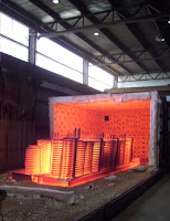
Custom Built Heat Treat Furnaces

Custom Built Heat Treat Furnaces
 15'x15'x60' Custom Furnaces
Hotfoil-EHS has extensive heat treating furnace design and fabrication experience. From small, low-throughput furnaces, to much larger high yield furnaces, to rail-driven furnaces, Hotfoil-EHS Design Engineers and Fabrication Shop have done it all.


 Heat Treat Furnace
Capable of handling 45,000 lbs.
Recently Hotfoil-EHS provided a customer with a heat treat furnace that is 15'x15'x60' that accommodates up to 45,000 pounds of material. Two, 5 million BTU burners heat the furnace to 1650 deg. F. The furnace travels on a track, back and forth, to accommodate two beds for greater production.

 Heat Treat Furnace
Rail system with (2) beds


For more information, visit http://www.hotfoilehs.com or call 609.588.0900.